在線客服
<samp id="aor1g"><video id="aor1g"></video></samp>
<samp id="aor1g"><video id="aor1g"></video></samp>
| Product Category Search |


.jpg)
Protection mode of over current protector
1, composite type: will be in line with a variety of protection.
2, limit power type: limited output of the total power.
3, rollback type: the initial current is constant, the voltage dropped to a certain value current begins to decrease.
4, vibration type: overcurrent, current and voltage drop to 0, and then began to rise again, again and again.
5, constant popular: current constant, voltage drop.
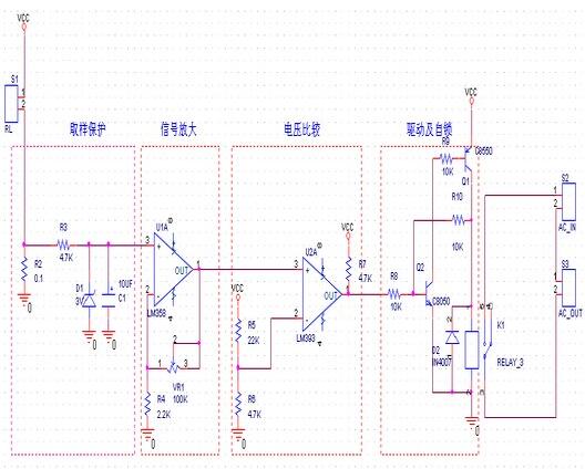
(Overcurrent protection circuit diagram)
When the power supply voltage or the load current is too large, the following circuit can disconnect the load to give the fault indication.
In normal operation, Tr1 and Tr2 are off, 555 reset, 555 in the discharge transistor, it is from the Tr3 base to draw current, so that Tr3 is open saturation, power supply 5 ~ 12V will be sent directly to the main load. Learn when the load current exceeds the prescribed value, the increase of pressure drop of Rsc, the Tr1 conduction, 555 is triggered, and the internal discharge transistor is turned off, follow the Tr3 deadline, the power supply and load isolation, while 555 in the single steady state, stability time, as long as the load flow phenomenon is not excluded, 555 again the trigger, Tr3 will continue to load isolation.
If the load appears over voltage, then the R4, R5, Tr2 after D1 conduction, also makes the 555 trigger, Tr3 then also load isolation.
For overcurrent or overvoltage, 555 feet will be the output of high potential, so that LED light, said the load is in a state of isolation. Because of the Tr3 or in the saturation, or at the end, so only a power transistor can work.

| Company Name: Shenzhen Tage Technology Co., Ltd. | |
| Phone: 86-755-88365418,88363521,88365225 | |
| Fax: 86-755-88361758 Holiday Service Phone: 18925218344 | |
| E-mail: evan@tergy.com | |
| Add: 6th Floor, Block E plant Bao‘an District of Shenzhen City streets by the people Minle Industrial Park South |


<samp id="aor1g"><video id="aor1g"></video></samp>
<samp id="aor1g"><video id="aor1g"></video></samp>
 銷售客服
銷售客服